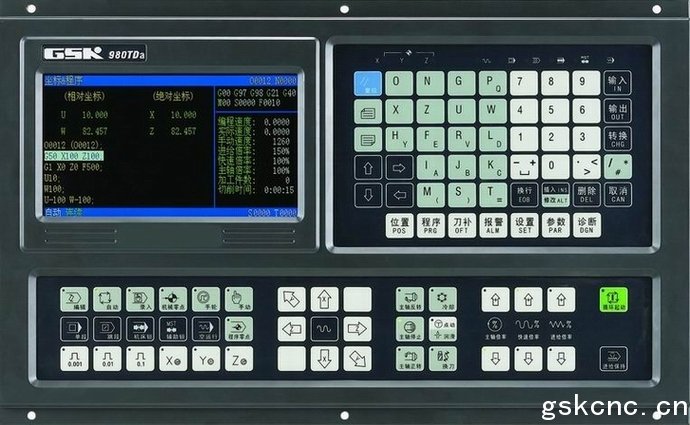
GSK980TDa CNC Lathe Controller
GSK980TDa is a new product based on GSK980TD, its display is 7” color wide-screen LCD, adds PLC axis control, Y control, parabola/circular interpolation, statement macro command, automatic chamfer, tool life management, tool wear compensation and so on. The added G31/G36/G37 can execute the jump and automatic tool compensation. The system clock can display the alarm log.
The system can be display in Chinese, English and Spanish. As the upgraded product of GSK980TD, GSK980TDa is the optimum option for the widespread CNC turning machine.
Controlled axes(X, Y, Z), link axes (X, Z), 0.001mm interpolation precision and max. rapid traverse speed 30,000 mm/min, linear/arc interpolation
Least command increment 0.001, electronic ratio (1~32767)/(1~32767)
Pitch error compensation, backlash compensation, tool length compensation, tool wear compensation and tool nose radius compensation
Embedded PLC, ladder edit in the PC to be downloaded to CNC
S, exponential acceleration/deceleration control to meet high speed and high precision machining
Tapping to machine metric/inch single/multiple straight, taper thread, end face thread, variable pitch thread, high speed thread run out with set retraction distance, angle and speed
Metric/inch programming, automatic chamfering, tool life management
Statement macro command programming, macro program call with parameters
Chinese and English display window selected by the parameter
Large memory capacity( 6144KB,384 part programs) with full screen edit
Clock, date, time power-on hold
Convenient management with multilevel operation password
Bidirectional communication between CNC and PC, CNC and CNC; upgrading communication CNC software and PLC programs
Installation dimension, electric interface, commands are compatible to GSK980TD
|
Motion control
|
Controllable axes: X, Z, Y; simultaneous controllable axes (interpolation axes): 2 (X, Z)
|
|
Interpolation: X, Z linear, arc interpolation
|
|
Maximum programmable dimensions: -9999.999 mm~9999.999mm, least command increment 0.001mm;
|
|
Electronic gear:command multiply 1~32767 and command division 1~32767
|
|
Rapid traverse speed: max. 30000mm/min
Rapid override: F0,25%,50%,100%
|
|
Cutting feedrate: max.15000mm/minor 500mm/rev(feedrate per rev)
Feedrate override: 16 steps 0~150%
|
|
Manual feedrate: 16 steps 0~1260mm/min
|
|
MPG feedrate: 0.001mm,0.01mm,0.1mm
|
|
Acceleration/deceleration: S acceleration/deceleration for rapid traverse, and exponential acceleration/deceleration for cutting feed
|
|
Automatic chamfering function
|
|
G
command
|
43 G commands: G00, G01, G02, G03, G04, G05, G6.2, G6.3, G7.2, G7.3, G10, G11, G20, G21, G28, G30, G31, G32, G33, G34, G36, G37, G40, G41, G42, G50, G65, G70, G66, G67, G71, G72, G73, G74, G75, G76, G90, G92, G94, G96, G97, G98, G99, macro command G65 to execute 27 kinds of calculation, logic operation and program skipping
|
|
Thread machining
|
Tapping: metric/inch, single/multiple, straight thread, taper thread, end face thread, variable pitch thread. Thread run out with set retraction distance, angel and speed; pitch: 0.001mm~500mm or 0.06~25400 tooth/ inch
|
|
Spindle encoder: lines can be set (100 p/r~5000p/r)
|
|
Drive ratio between encoder and spindle: (1~255):(1~255)
|
|
Precision compensation
|
Backlash compensation: 0mm~2.000mm
|
|
Pitch error compensation: 255 compensation points/axis, compensation
value/point:±0.255mm×compensation override
|
|
Tool compensation: 32 groups tool length compensation, tool nose radius compensation (tool compensation C)
Toolsetting method: fixed-point, trial cutting
Tool compensation executing methods: traversing tool or coordinate offset
|
|
M
command
|
M commands(no repetition): M02, M30, M98, M99, M9000~M9999
Other M□□ commands are defined and executed by PLC programs
|
|
M commands defined by standard PLC program: M00, M03, M04, M05, M08,
M09, M10, M11, M12, M13, M32, M33, M41, M42, M43, M44
|
|
T
command
|
Most 32 tool selections(T01□□~T32□□), the time sequence of tool change is defined by PLC programs. The tool selection is set to 1 and the tool change is not executed by PLC when the line-up tool post is used; tool life management.
|
|
Spindle speed
|
Speed switching value control: S□□ command is defined and executed by PLC programs, S1, S2, S3 and S4 is specified by standard PLC programs directly output, and S0 closes S1, S2, S3, S4 output.
|
|
Speed analog voltage control: S commands specifying the spindle speed per minute or the cutting surface speed (constant surface speed control) , 0~10V voltage to spindle converter, 4 gears spindle speed with stepless shifting gear
|
|
PLC
function
|
9 elementary commands, 23 functional commands, 2-level PLC program, max. 5000 steps, execution time 2μs for each step, refresh cycle 8ms for 1st level program; each axis specified to be PLC controlled axis; ladder diagram editing software, PLC program communication download
|
|
PLC
function
|
Integrated machine control panel: 41 input points (press keys), 42 output points (LED)
I/O interfaces: 16 input points /16 output points, up to 32 input signals/32 output signals
|
|
Displaying window
|
Display: 480×234 lattice, 7” color wide-screen liquid crystal display(LCD)
|
|
Display method: Chinese or English or Spanish or Russian window is set by a parameter, displaying machining path of workpiece
|
|
Program edit
|
Program capacity: 6144KB, max. 384 programs, customer macro program cal and four-embedded subprogram
|
|
Editing method: edit in full screen. Statement macro command programming; incremental coordinates, absolute coordinate and compound coordinates programming
|
|
Communication
|
Two-way communicating programs and parameters between CNC and PC, CNC and CNC; communication upgrade, PLC programs serial download upgrade
|
|
Optional drive unit
|
DA98 series digital AC servo drive unit or DY3 series stepper drive unit with input pulse and direction signal
|
G Commands
|
Commands
|
Functions
|
Commands
|
Functions
|
|
G00
|
Rapid traverse
|
G50
|
Coordinate system setting
|
|
G01
|
Linear interpolation
|
G65
|
Macro command
|
|
G02
|
CW arc interpolation
|
G70
|
Finishing cycle
|
|
G03
|
CCW arc interpolation
|
G71
|
Axial roughing cycle
|
|
G04
|
Dwell
|
G72
|
Radial roughing cycle
|
|
G10
|
Data input ON
|
G73
|
Closed cutting cycle
|
|
G11
|
Data input OFF
|
G74
|
Axial grooving cycle
|
|
G20
|
Input in inch
|
G75
|
Radial grooving cycle
|
|
G21
|
Input in metric
|
G76
|
Multiple thread cutting cycle
|
|
G28
|
Reference point return
|
G90
|
Axial cutting cycle
|
|
G30
|
Return to 2nd, 3rd, 4th reference point
|
G92
|
Thread cutting cycle
|
|
G32
|
Variable thread cutting
|
G94
|
Radial cutting cycle
|
|
G33
|
Z tapping cycle
|
G96
|
Constant surface speed control
|
|
G34
|
Thread cutting with variable lead
|
G97
|
Constant surface speed control cancel
|
|
G40
|
Canceling tool nose radius compensation
|
G98
|
Feed per minute
|
|
G41
|
Tool nose radius compensation left of contour
|
G99
|
Feed per rev
|
|
G42
|
Tool nose radius compensation right of contour
|
|
|
Macro Command List GSK980TDa adds the statement macro command function with G65 macro command function of GSK980TD. The macro command format list of G65 statement is as follows:
|
Function
|
G65 macro command format
|
Statement macro command format
|
|
Assigned value
|
G65 H01 P#i Q#j;
|
#i=#j;
|
|
Decimal addition operation
|
G65 H02 P#i Q#j R#k;
|
#i=#j+#k;
|
|
Decimal subtraction operation
|
G65 H03 P#i Q#j R#k;
|
#i=#j-#k;
|
|
Decimal multiplication operation
|
G65 H04 P#i Q#j R#k;
|
#i=#j*#k;
|
|
Decimal division operation
|
G65 H05 P#i Q#j R#k;
|
#i=#j/#k;
|
|
Binary addition (operation)
|
G65 H11 P#i Q#j R#k;
|
#i=#j OR #k;
|
|
Binary multiplication (operation)
|
G65 H12 P#i Q#j R#k;
|
#i=#j AND #k;
|
|
Binary OR
|
G65 H13 P#i Q#j R#k;
|
#i=#j XOR #k;
|
|
Decimal square root
|
G65 H21 P#i Q#j;
|
#i=SQRT (#j) ;
|
|
Decimal absolute value
|
G65 H22 P#i Q#j;
|
#i=ABS (#j) ;
|
|
Decimal remainder
|
G65 H23 P#i Q#j R#k;
|
none
|
|
ROUND function
|
none
|
#i=ROUND (#j) ;
|
|
Rounding up to an integer
|
none
|
#i=FUP (#j) ;
|
|
Rounding down to an integer
|
none
|
#i=FIX (#j) ;
|
|
Natural logarithm
|
none
|
#i=LN (#j) ;
|
|
Exponential function
|
none
|
#i=EXP (#j) ;
|
|
Decimal to binary
|
G65 H24 P#i Q#j;
|
#i=BIN (#j) ;
|
|
Binary to decimal
|
G65 H25 P#i Q#j ;
|
#i=BCD (#j) ;
|
|
Decimal multiplication/division operation
|
G65 H26 P#i Q#j R#k;
|
none
|
|
Multiplex square root
|
G65 H27 P#i Q#j R#k;
|
none
|
|
Sine
|
G65 H31 P#i Q#j R#k;
|
#i=SIN (#j) ;
|
|
Inverse sine
|
none
|
#i=ASIN (#j) ;
|
|
Cosine
|
G65 H32 P#i Q#j R#k;
|
#i=COS (#j) ;
|
|
Inverse cosine
|
none
|
#i=ACOS (#j) ;
|
|
Tangent
|
G65 H33 P#i Q#j R#k;
|
#i=TAN (#j) ;
|
|
Inverse tangent
|
G65 H34 P#i Q#j R#k;
|
#i=ATAN (#i)/(#j) ;
|
|
Unconditional jump
|
G65 H80 Pn;
|
GOTO n;
|
|
Unconditional jump 1
|
G65 H81 P#i Q#j R#k;
|
IF (#j==#k) GOTO n; or
IF (#j EQ #k) GOTO n;
|
|
Unconditional jump 2
|
G65 H82 P#i Q#j R#k;
|
IF (#j<>#k) GOTO n; or
IF (#j NE #k) GOTO n;
|
|
Unconditional jump 3
|
G65 H83 P#i Q#j R#k;
|
IF (#j>#k) GOTO n; or
IF (#j GT #k) GOTO n;
|
|
Unconditional jump 4
|
G65 H84 P#i Q#j R#k;
|
IF (#j<#k) GOTO n; or
IF (#j LT #k) GOTO n;
|
|
Unconditional jump 5
|
G65 H85 P#i Q#j R#k;
|
IF (#j>=#k) GOTO n; or
IF (#j GE #k) GOTO n;
|
|
Unconditional jump 6
|
G65 H86 Pn P#i R#k;
|
IF (#j<=#k) GOTO n; or
IF (#j LE #k) GOTO n;
|
|
User alarm
|
G65 H99 Pn;
|
|
|
Conditional control
|
|
IF (conditional expression)
THEN macro program statement
|
|
IF (conditional expression) GOTO n;
|
|
Cycle control
|
none
|
WHILE (conditional expression) DO m;
…
END m;
…
|
PLC Command List
|
Name
|
Function
|
Name
|
Function
|
|
LD
|
Read normally-open contact
|
CODB
|
Binary conversion
|
|
LDI
|
Read normally-closed contact
|
ROTB
|
Binary rotation control
|
|
OUT
|
Output coil
|
MOVN
|
Data copy
|
|
AND
|
Normally-open contact in series
|
DECB
|
Binary decoding
|
|
ANI
|
Normally-closed contact in series
|
JMPB
|
Program jumping
|
|
OR
|
Parallel normally-open contact
|
SP
|
Subprogram label
|
|
ORI
|
Parallel normally-closed contact
|
SPE
|
End of subprogram
|
|
ORB
|
Parallel series circuit block
|
ADDB
|
Binary addition
|
|
ANB
|
Parallel circuit block in series
|
SUBB
|
Binary subtracting
|
|
END1
|
End of grade one program
|
ALT
|
Alternative output
|
|
END2
|
End of grade two program
|
DIFU
|
Rising edge detection
|
|
SET
|
Set
|
DIFD
|
Falling edge detection
|
|
RST
|
Reset
|
MOVE
|
Logical AND
|
|
CMP
|
Comparative set
|
PARI
|
Parity check
|
|
CTRC
|
Counter
|
LBL
|
Program jump label
|
|
TMRB
|
Timer processing
|
CALL
|
Subprogram call
|
|
GSK980TDa-B
|
GSK980TDa matching with AP01(445mm×345mm×182mm)
|
|
Type
|
Specification
|
|
GSK980TDa
|
420mm×260mm aluminum alloy operator panel
|
● Standard functions
All functions in the provided technical specifications include: Max. rapid traverse speed 30,000 mm/min, max. feedrate 15,000 mm/min, pitch error compensation, tool nose radius compensation, tool life management, automatic chamfering, PLC axis control, spindle analog voltage control(converter spindle),communication, 32 input signals and 32 output signals.
Standard PLC ladder supporting the electric tool post with 2~8 tool selections, Yantai AK31, Changzhou SWBD tool post, and 4-gear spindle automatic shifting gear(only test 1st and 2nd gear), hydraulic chuck, hydraulic tailstock, safeguard, three-color lamp, external MPG(adapted to PSG-100-05E/L、ZSSY2080) and so on.
● Standard accessories
Switch power: GSK-PB2(assembled at the back of CNC)
Connector assembly: CNC interfaces are connected by one set of plug( DB9 female×2, DB15 male×3, DB25 female×2, DB25 male×2)
Note: Corresponding plugs along with cables are supplied when they along with other components including drive unit are delivered.
Accessory cables: 12m 10-core shield cable( X, Y, Z axis, input interface XS40/XS41, output interface XS39/XS42);
9m 8-core shield cable (spindle encoder, input interface XS40/XS41, output interface XS39/XS42);
3m 4-core shield cable (converter interface);
Note: The above-mentioned cables as wires(not be welded) are supplied. Signal cables with welded plugs are supplied when a whole set of drive unit and the tool post controller are delivered. The requirements for cable length and welding should be remarked in the order list.
Technical documents: GSK980TDa Turning Machine CNC System User Manual(without PLC User Manual)
● Optional accessories
Communication cable A: serial communication cable 5m×1 between PC and CNC(for end user and machine tool manufacturer)
Communication cable B: serial communication cable 5m×1 between CNC and CNC (for machine tool manufacturer used for installing and debugging the system)
Communication disc: communication software TDComm installation disc ×1
Ladder programming software: GSKCC installation disc ×1
MPG: Dongxin RE45T1S05B1(option: AP01) or Changchun LGF-001-100(option: AP02);
Additional panel:AP01(aluminum alloy 420×71㎜) can be assembled under of GSK980TD operator panel;
AP02(aluminum alloy 100×260㎜)can be assembled at the side of GSK980TD operator panel;
Emergent stop button: LAY3-02ZS/1( it has been installed when GSK980TDa-B is delivered);
No self-locking button: KH-516-B11(green or red);
Self-locking button: KH-516-B21(green or red);
I/O transfer terminal block:MCT03
Note: one set of I/O transfer cable (with 26-core shield cable, DB25 male/female socket) when MCT03 is matched
● Order
Remarks in the order:
a) Product type(GSK980TDa, GSK980TDa-B), quantity
b) Type and number of assembly (drive unit, isolated transformer)
c) Length and connection of accessory cable
d) Name, type, quantity, installation & connection requirements of optional accessories
Whether PLC program(ladder) is provided with special requirements.
GSK980TDa Turning Machine CNC Rear Interface Layout
● GSK980TDa Appearance Dimension
Optional accessories
Additional panel AP01
Additional panel AP02
I/O splice transfer terminal block MCT03
● GSK980TDa-B Appearance Dimension
GSK980TDa Turning CNC controller user manual:
http://www.Gskcnc.cn/uploads/soft/100630/GSK980TDa_CNC_Turning_Controller_User_Manual_I.rar
http://www.Gskcnc.cn/uploads/soft/100630/GSK980TDa_CNC_Turning_Controller_User_Manual_II.rar
GSK980TDa PLC user manual:
http://Gskcnc.cn/uploads/soft/100630/GSK980TD_CNC_Turning_Controller_PLC_User_Manual.rar
GSK980TDa communicator software download:
http://www.Gskcnc.cn/uploads/soft/100630/GSK980TDa_CNC_Turning_Controller_Communicator.rar
|